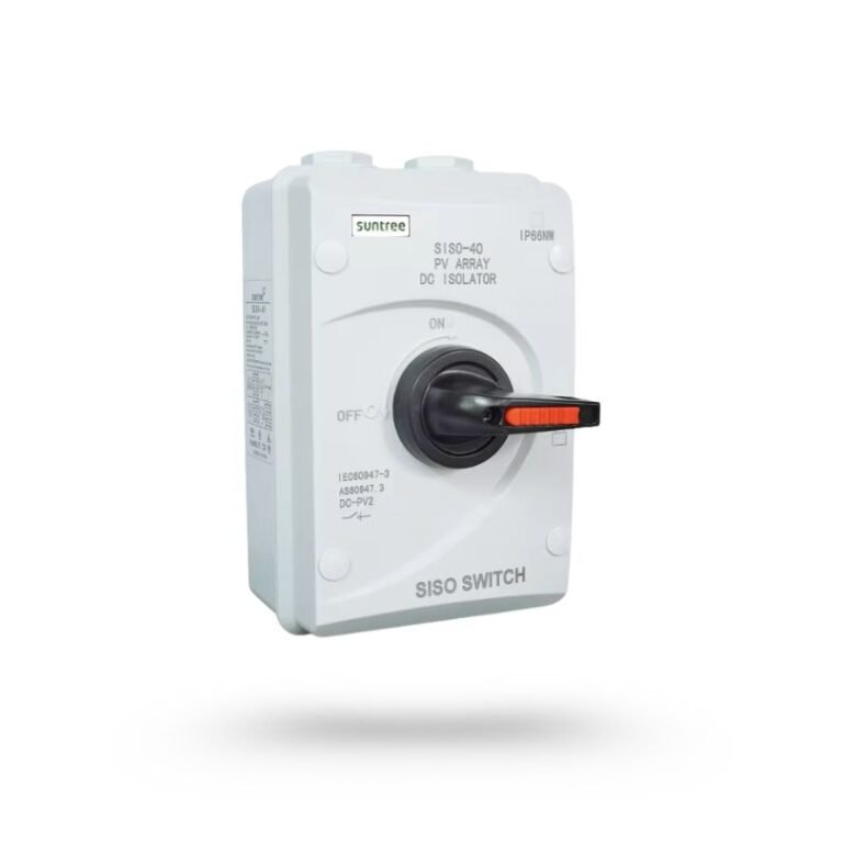
What it does—and where it belongs
A switch-disconnector is chosen to make and break the expected DC load and provide isolation. It is an operational safety device, not normally the device that detects an overload.
Close to the inverter DC input and, where design or local rules require it, at array or combiner locations. Some inverters incorporate a compliant DC switch, but system-level isolation still needs review.
What to check before you buy
PV load-break capability
Ask for the device utilisation category and DC switching data, not merely a large number printed on the enclosure.
Correct pole wiring
Series poles are often used to interrupt higher DC voltages. Use only the maker's approved diagram.
Independent enclosure rating
For rooftop or outdoor locations, check UV stability, ingress protection, gland arrangement and operating temperature.
Lockable OFF position
A clear, lockable position improves safe maintenance and reduces accidental re-energisation.
Red flags in a quotation or site visit
- AC-22 or AC-23 marking offered as proof of PV DC suitability
- No DC wiring diagram
- Exposed top cable entry without a weatherproof gland plan
- Handle can indicate OFF before the contacts have safely opened
Commissioning checks to request
Ask the installer to verify
- Switch is accessible without entering an unsafe roof area
- Cable entries do not allow water tracking into the enclosure
- The switch is not installed under mechanical cable strain
- ON/OFF labels and circuit identification remain readable
Common mistakes
- —Treating an isolator as overcurrent protection
- —Selecting from inverter operating voltage instead of maximum string Voc
- —Ignoring thermal derating in a sun-heated enclosure
- —Switching under a condition not covered by the device rating
A better quotation line item
PV DC switch-disconnector, load-break rated, ___ poles, ___ A at ___ V DC in the maker-approved PV configuration, lockable OFF, enclosure IP___ and UV-resistant where outdoors, compliant with IEC 60947-3.
This wording is a procurement prompt, not a final engineering specification. Values must come from the approved single-line diagram and equipment manuals.
Standards and sources checked
Requirements for switches, disconnectors and switch-disconnectors, including critical DC load tests.
PV array design requirements covering DC wiring, protection, switching and earthing.
Selection and application requirements for equipment in PV electrical installations.
Pakistan project note: ask the installer to confirm the current PSQCA-adopted standard, inverter instructions, earthing rules and the latest DISCO/NEPRA interconnection requirements applicable to your site.
Questions about DC isolator
Is the inverter's built-in DC switch enough?
It may be, but only after checking the inverter manual, the array layout, maintenance access and local requirements. A remote array or combiner can still need another isolation point.
Can I turn the isolator off under load?
Only a correctly selected load-break switch may interrupt its rated current and voltage. Follow the system shutdown sequence and the manufacturer's instructions.