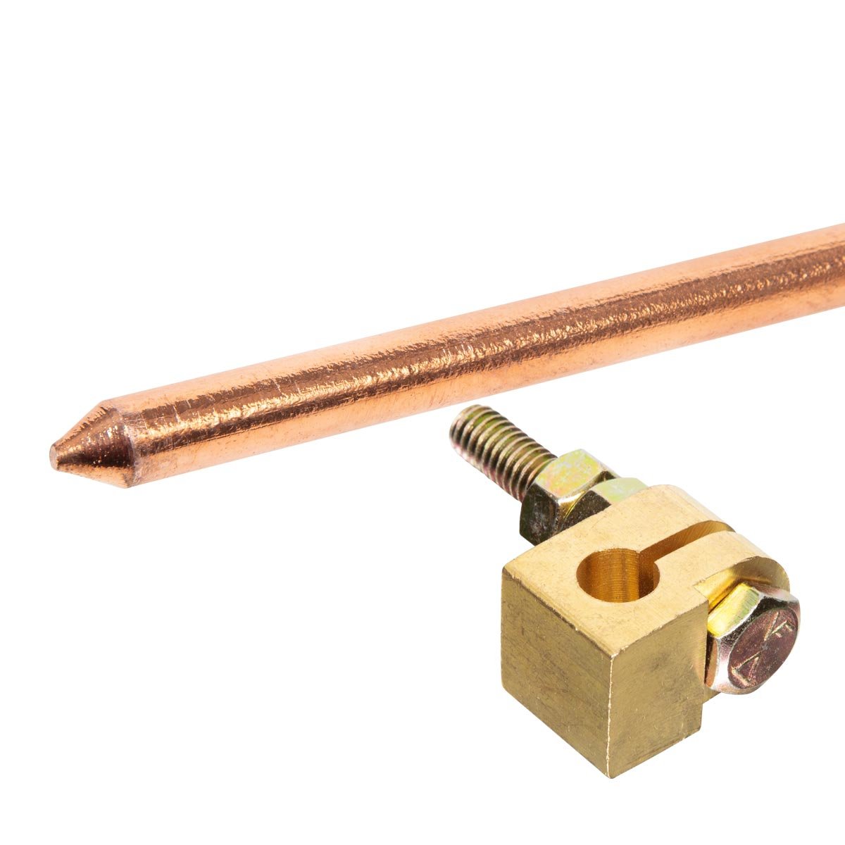
What it does—and where it belongs
Protective earthing, equipotential bonding, functional earthing and lightning protection are related but not interchangeable. The design must match the building earthing arrangement, inverter/module instructions, soil conditions and lightning risk.
Across module frames and mounting metalwork, inverter and distribution equipment, protective conductors, earth electrodes and any external lightning protection system.
What to check before you buy
A design, not a rod count
Ask for an earthing/bonding drawing, conductor sizes, connection hardware and test method. 'Three rods' is not an engineering specification.
Compatible metals
Clamps and lugs must avoid galvanic corrosion between aluminium frames, copper conductors, steel structures and the local environment.
Lightning separation
If the building has external lightning protection, array placement, bonding and SPDs must be coordinated with its separation-distance design.
Testable joints
Critical connections and electrodes should be inspectable and included in periodic maintenance.
Red flags in a quotation or site visit
- Independent earth rods are added without bonding-system review
- Copper wire is wrapped directly around aluminium rail
- An SPD has a long, thin earth lead
- No commissioning test values are handed over
Commissioning checks to request
Ask the installer to verify
- Frame/rail bonding is continuous across removable sections
- Connections use listed lugs/clamps and corrosion control
- Earth electrode and protective-conductor results are recorded
- Lightning protection and SPD drawings agree with actual routing
Common mistakes
- —Confusing neutral with protective earth
- —Chasing one universal resistance value without system context
- —Creating dangerous potential differences with isolated electrodes
- —Painting or anodised surfaces prevent effective bonding
A better quotation line item
PV protective-earthing and lightning-protection design showing bonding points, conductor material/size, compatible listed clamps, electrode arrangement, SPD connection paths and commissioning test values, coordinated with IEC 62548 and IEC 62305.
This wording is a procurement prompt, not a final engineering specification. Values must come from the approved single-line diagram and equipment manuals.
Standards and sources checked
General principles for protection of structures, installations and people against lightning.
PV array design requirements covering DC wiring, protection, switching and earthing.
Selection and application requirements for equipment in PV electrical installations.
Documentation, inspection and commissioning-test framework for grid-connected PV systems.
Pakistan project note: ask the installer to confirm the current PSQCA-adopted standard, inverter instructions, earthing rules and the latest DISCO/NEPRA interconnection requirements applicable to your site.
Questions about Earthing & LPS
How many earth rods does a solar system need?
There is no universal number. Electrode design depends on the existing earthing arrangement, soil, fault protection, lightning design and measured results.
Should panels have a separate earth?
Module frames and structures normally need equipotential bonding, but creating a separate uncoordinated electrode can be hazardous. Integrate it with the building design.