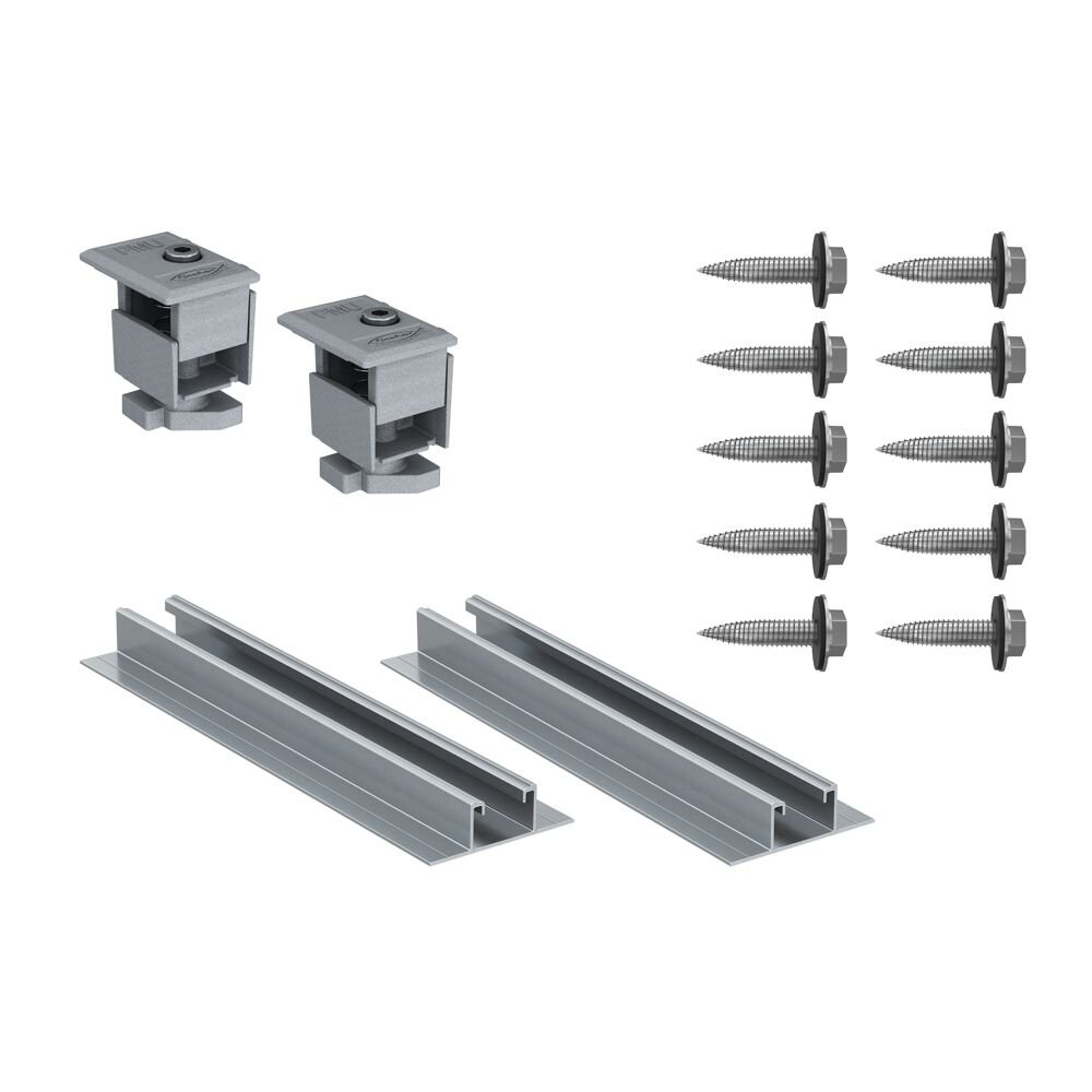
What it does—and where it belongs
The racking system sets module orientation, edge/clamp zones, ventilation and structural load paths. It must be engineered for the specific roof, wind exposure, module dimensions and local corrosion environment.
On concrete roofs, sheet-metal roofs, carports or ground foundations, with interfaces to the module frames and the building structure.
What to check before you buy
Site-specific calculation
Ask for design loads, member checks, anchor reactions and assumptions. A photo of another roof is not structural evidence.
Roof interface
Waterproofing, edge distances, concrete quality, sheet profile and load path into the building need explicit details.
Material traceability
Specify metal grade, thickness, coating/galvanising and fastener grade—not simply 'L2' or 'heavy structure'.
Module approval
Rail spacing, clamp type, clamp length and torque must remain inside the module maker's approved zones.
Red flags in a quotation or site visit
- Same structure promised for every roof and city
- No wind-load or anchor calculation
- Uncoated cut edges or mixed metals
- Panels extend beyond supports outside their approved cantilever
Commissioning checks to request
Ask the installer to verify
- Anchors match drawing and substrate
- All clamps are in approved zones and torqued
- Roof drainage and maintenance paths remain open
- Corrosion protection is repaired at cuts/drilled areas
Common mistakes
- —Adding excessive tilt without checking wind uplift
- —Anchoring only into screed or thin sheet
- —Blocking roof drains
- —Using module frames as walkways
A better quotation line item
Engineered PV mounting system for module ___ × ___ mm, array layout ___, roof/substrate ___, site wind/load assumptions ___, material grade/coating ___, anchor schedule and reactions ___, compatible module clamp zones and corrosion-isolation details.
This wording is a procurement prompt, not a final engineering specification. Values must come from the approved single-line diagram and equipment manuals.
Standards and sources checked
PV array design requirements covering DC wiring, protection, switching and earthing.
General principles for protection of structures, installations and people against lightning.
Documentation, inspection and commissioning-test framework for grid-connected PV systems.
Pakistan project note: ask the installer to confirm the current PSQCA-adopted standard, inverter instructions, earthing rules and the latest DISCO/NEPRA interconnection requirements applicable to your site.
Questions about Mounting structure
Which is better, aluminium or galvanised steel?
Either can be appropriate. The answer depends on structural efficiency, coating/grade, connection details, environment, maintenance and lifecycle—not material name alone.
What tilt angle should the structure use?
Energy yield is only one factor. Wind load, self-shading, roof area, drainage, access and structural capacity can make a lower tilt the safer overall design.